The crankshaft position sensor is positioned so that teeth on the reluctor ring attached to the crankshaft pass close to the sensor tip. The reluctor ring has one or more teeth missing to provide the engine computer (PCM) with the reference point to the crankshaft position.
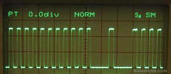
As the crankshaft rotates, the sensor produces a pulsed voltage signal, where each pulse corresponds to the tooth on the reluctor ring. The photo below shows the actual signal from the crankshaft position sensor with the engine idling. In this vehicle, the reluctor ring is made with two missing teeth, as you can notice on the graph.
The PCM uses the signal from the crankshaft position sensor to determine at what time to produce the spark and in which cylinder. The signal from the crankshaft position is also used to monitor if any of the cylinders misfires.
 Crankshaft position sensor signal on the oscilloscope screen.
If the signal from the sensor is missing, there will be no spark and fuel injectors won’t operate.
The two most common types are the magnetic sensors with a pick-up coil that produce A/C voltage and the Hall-effect sensors that produce a digital square wave signal as in the photo above. Modern cars use the Hall-effect sensors. A pick-up coil type sensor has a two-pin connector. The Hall-effect sensor has a three-pin connector (reference voltage, ground and signal).
$25,534.00
The crankshaft position sensor is positioned so that teeth on the reluctor ring attached to the crankshaft pass close to the sensor tip. The reluctor ring has one or more teeth missing to provide the engine computer (PCM) with the reference point to the crankshaft position.
As the crankshaft rotates, the sensor produces a pulsed voltage signal, where each pulse corresponds to the tooth on the reluctor ring. The photo below shows the actual signal from the crankshaft position sensor with the engine idling. In this vehicle, the reluctor ring is made with two missing teeth, as you can notice on the graph.
The PCM uses the signal from the crankshaft position sensor to determine at what time to produce the spark and in which cylinder. The signal from the crankshaft position is also used to monitor if any of the cylinders misfires.
 Crankshaft position sensor signal on the oscilloscope screen.
If the signal from the sensor is missing, there will be no spark and fuel injectors won’t operate.
The two most common types are the magnetic sensors with a pick-up coil that produce A/C voltage and the Hall-effect sensors that produce a digital square wave signal as in the photo above. Modern cars use the Hall-effect sensors. A pick-up coil type sensor has a two-pin connector. The Hall-effect sensor has a three-pin connector (reference voltage, ground and signal).
| Type | 37500-PLC-015, 37500-RAA-A01 |
|---|---|
| Compatible with | 20T2N, D16B6, D16B7, F18B2, F18B3, F20B6, F23Z5, H22A7, EE2, D14Z5, D14Z6, D15Y2, D15Y3, D15Y4, D15Y5, D15Y6, D16V1, D16V2, D16V3, D16W7, D16W8, D16W9, D17A, D17A2, D17A5, D17A8, D17A9, D17Z1, D17Z4, D17Z5, K20A2, K20A3, MG117, MG217, PSGD02, PSGD53, PSHD58, PSJD04, PSJD06, PSJD55, PSJD57, K20A9, N22A1, R18A1, K20A1. |
Get E-mail updates about our latest products and special offers.
Sensors and More is Jamaica’s ultimate online auto parts store. Established in 2020, we specialize in genuine electrical parts for Japanese, Read more…
Reviews
There are no reviews yet.